 |
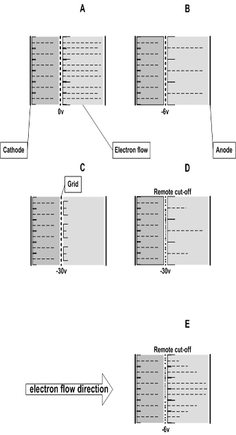
In drawing B a bias voltage of -6 volts is applied to the grid. You can see some of the electron flow is attracted to the negatively charged grid wires while the rest pass through the grid spacings. Since there are fewer electrons reaching the anode, conduction through the tube is decreased. In drawing C a greater negative potential is applied to the grid this is now -30 volts, this drives the tube into cutoff. All the electron flow terminates at the negatively charged grid, instead of continuing on to the anode. The electrons emitted by the cathode will not feel the electrostatic force so attractive with the positively charged anode. Under these conditions current cannot flow through the tube. Now look at drawings D and E, here you see electron flow of the variable-mu, or remote cutoff tubes. The only difference in these examples between the remote cutoff tube shown and the sharp-cutoff tube is in the grid wire spacing. In the conventional sharp-cutoff tube, the grid wires are evenly spaced, while in the remote cutoff tube the grid wires in the middle of the grid are placed relatively far apart..
Remote cutoff tubes require a higher bias voltage to stop conducting. The change in the amount of current passed tends to follow a curve where there is a greater effect in the lower part of the range of bias voltages than the upper. It is common for the first 25% of bias voltages to produce 50% or more change in the amount of current passed. By the time a bias of three-quarters of the cutoff voltage is reached, the tube may operate at 5% of the rated current. |
|