TOP VIEW
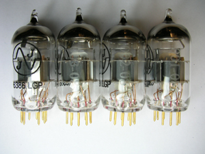
New generation 6386 tubes
|
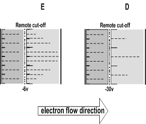
The remote cut-off action is due to the structure of the grid, which provides a variation in gain with a change in bias. The control grid is wound with a wide spacing at the center and a close spacing at the top and bottom. In drawing E small signals and low grid bias are applied to the tube, the effect of the non-uniform grid spacing between windings on cathode emission and tube characteristics are essentially the same as for uniform spacing. In drawing D the grid bias is made more negative to handle larger input signals, the electron flow from the sections of the cathode enclosed by the edges of the grid are cut off. The plate current and other characteristics are then dependent on the electron flow through the middle and relatively open sections of the grid. This action reduces the gain of the tube so that larger signals may be handled with minimum distortion. Determining gain in the manufacture of a tube The transconductance (gm) is most affected by the size of the cathode, while mu and rp are largely affected by grid location and the spacing of the grid a wirewound helix. A closely-wound grid or one close to the cathode, will have greater effect on the cathode field and a higher mu than an open-wound grid. gm and rp are almost inversely related. As gm increases with increasing plate current, rp proportionately decreases. This inverse relationship causes mu to be virtually a constant that typically varies less than 10-15%. mu = gm x rp gm is Transconductance mu is Amplification factor rp is Dynamic plate resistance |
|

